ncWirelessIO
ncWirelessIO gives ncSender four inputs, four switched outputs and a machine-status LED strip port, linked wirelessly through the Wireless USB →. Mount it at the tool changer and wire the sensors and the air solenoid there, instead of running cables back to the control box. Your controller's own inputs and outputs stay free.
It is built for ncSender's Pneumatic ATC → plugin: a drawbar sensor, a tool sensor and the clamp solenoid. The two spare inputs and three spare outputs are yours for anything else.
Coming soon
ncWirelessIO is in development. Pneumatic ATC support for it arrives with the plugin's ncWirelessIO profile.
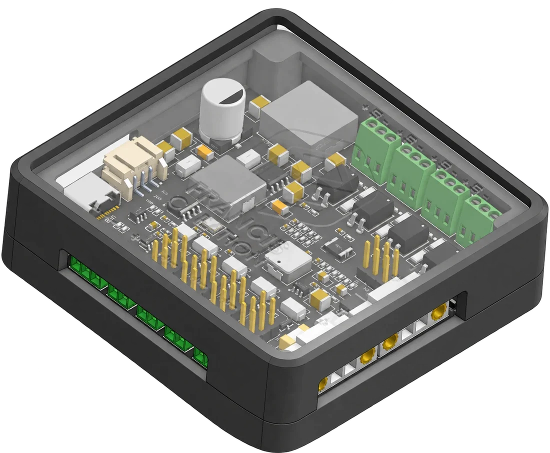
Hardware
- 4 inputs, optically isolated, for 3.3–24 V signals. NPN sensors, PNP sensors and plain switches all work.
- 4 switched outputs, each set to 5, 12 or 24 V with its own jumper. Short-circuit and over-temperature protected.
- LED strip port for a 12 V WS2811 strip. It shows machine state the same way the RGB LED → does.
- 24–48 V DC supply, reverse-polarity protected.
- USB-C for set-up and fast firmware updates.
- Pairs with the Wireless USB →, the same one the pendant, AutoDustBoot and RGB LED use.
Wireless USB is required
ncWirelessIO only talks to ncSender through the Wireless USB →.
What's on the board
Everything is printed on the board. The numbers below match the picture.
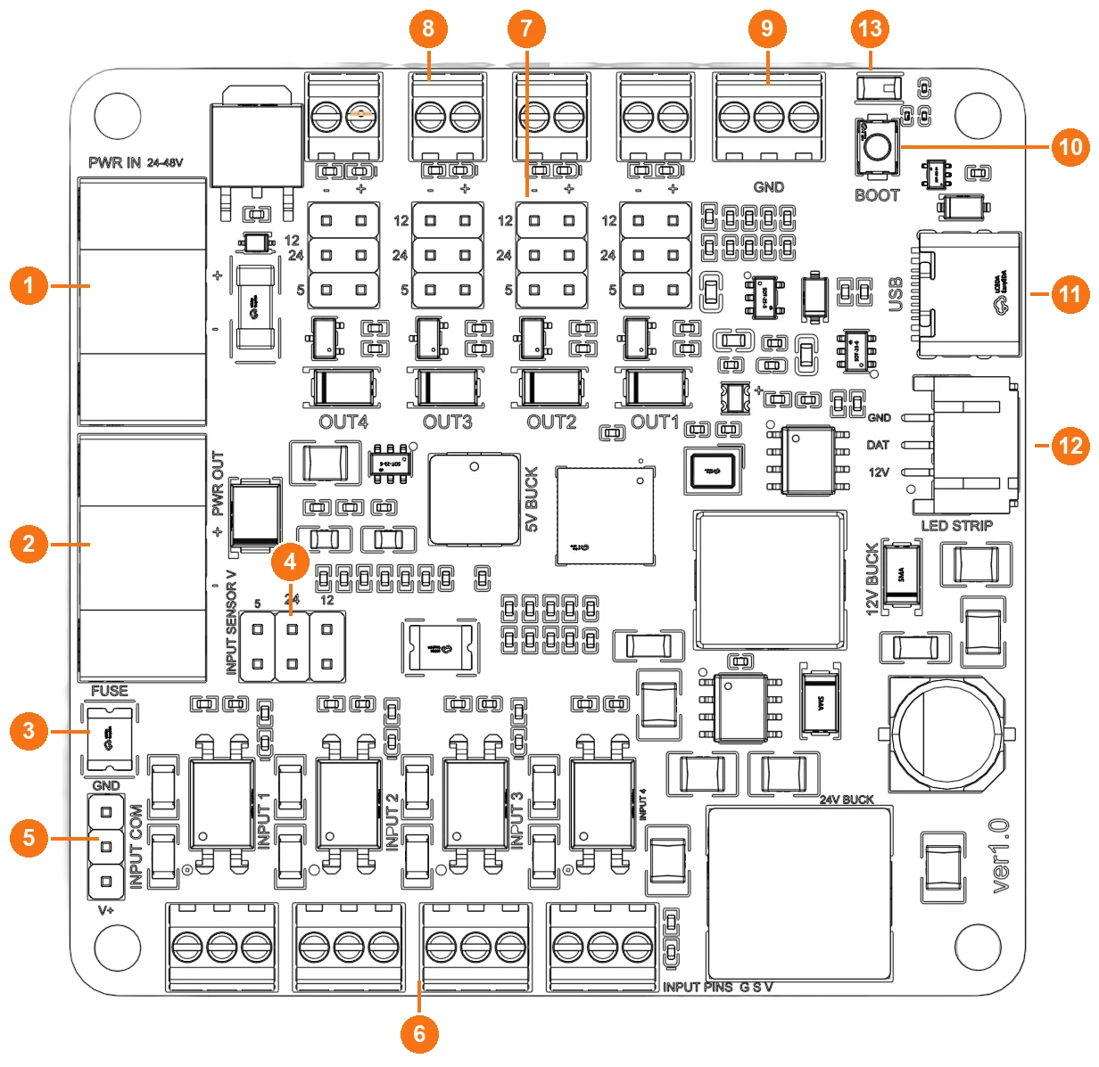
| # | Label on the board | What it is |
|---|---|---|
| 1 | PWR IN + − |
Power in, 24–48 V DC |
| 2 | PWR OUT + − |
The same supply passed on to another device (optional) |
| 3 | FUSE | Resettable fuse for the sensor supply |
| 4 | INPUT SENSOR V 5 24 12 |
Jumper: the voltage on every input's V screw |
| 5 | INPUT COM GND … V+ |
Jumper: PNP or NPN sensors |
| 6 | INPUT 1 … INPUT 4 (left to right) | Input terminals. INPUT PINS: G S V is printed beside them |
| 7 | Output jumpers, rows 12 24 5 |
One per output, above its terminal: that output's voltage |
| 8 | Output terminals − + |
One per output. From the left: OUT4, OUT3, OUT2, OUT1 (printed below the jumpers) |
| 9 | GND | Three spare ground screws |
| 10 | BOOT | Pairing button |
| 11 | USB | USB-C |
| 12 | LED STRIP GND DAT 12V |
Plug for the LED strip |
| 13 | Status light | Shows machine state and pairing (see Status light) |
The underside repeats the terminal names (INPUT 1 … and V S G, mirrored), so
you can check your wiring with the board turned over.
Power
Connect a 24–48 V DC supply to PWR IN: + to the supply's positive,
− to its negative.
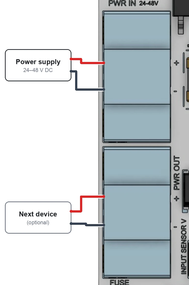
- Wired backwards, the board stays off and nothing is damaged. Swap the wires.
- PWR OUT passes your supply straight on, exactly as it is wired, so you can power another accessory (an RGB LED or AutoDustBoot controller) without a second run back to the supply. It is not fused or protected by ncWirelessIO, so check the polarity before you connect the next device.
- With a 24 V supply, outputs set to
24get slightly less than 24 V. Use a 36 V or 48 V supply if a 24 V load needs a full 24 V. - USB-C alone powers the brain of the board, enough to set it up and update it. Inputs, outputs and the LED strip need PWR IN.
Inputs
Each input has a 3-screw terminal:
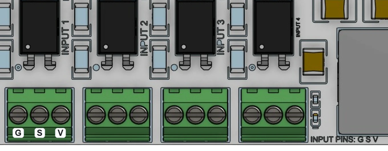
| Screw | Name | Wire it to |
|---|---|---|
G |
Ground | The sensor's ground or 0 V wire |
S |
Signal | The sensor's output wire, or one side of a switch |
V |
Sensor supply | The sensor's power wire, or the other side of a switch |
Each input has a blue light near its terminal. It is on while the input is active, so you can check a sensor without opening ncSender.
Sensor supply jumper (INPUT SENSOR V)
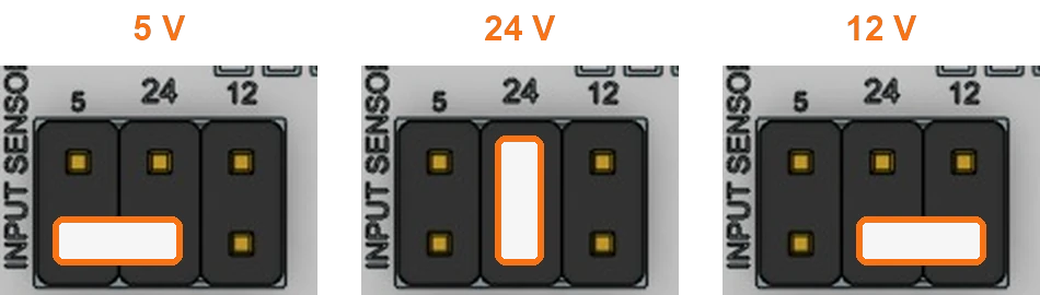
The V screw on all four inputs carries the same voltage. Choose it with the
INPUT SENSOR V jumper (4 in the picture). Its columns are printed 5,
24 and 12:
| Voltage | Shunt position |
|---|---|
| 5 V | Bottom row, left pair (under 5 and 24) |
| 24 V | Middle column, top to bottom (under 24) |
| 12 V | Bottom row, right pair (under 24 and 12) |
Pick the voltage your sensors are rated for. Most inductive proximity sensors take 12–24 V. The sensor supply is protected by a resettable fuse (FUSE). It cuts out on a short and comes back once the short is removed.
NPN or PNP (INPUT COM)
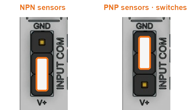
The INPUT COM jumper (5 in the picture) sets the sensor type for all
four inputs. Its three pins run top to bottom: GND, COM, V+.
| Shunt position | Use it for |
|---|---|
| Bottom two pins (COM and V+) | NPN sensors (they switch their output to ground) |
| Top two pins (COM and GND) | PNP sensors (they switch their output to the supply), and plain switches |
Mixing types? Use the setting that suits most of them. A plain switch works on
either setting if you wire it between S and the right screw: S–V with
COM on GND, or S–G with COM on V+.
Sample wiring
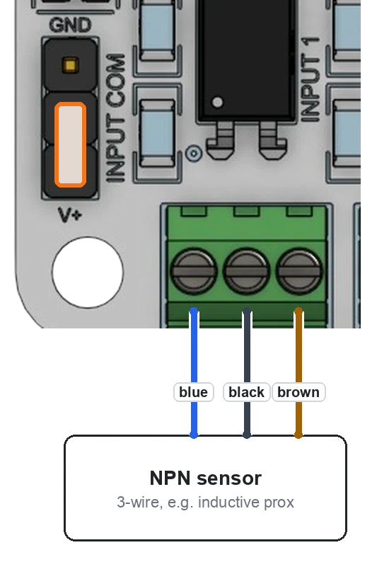
- INPUT COM on the bottom two pins (V+ side).
- INPUT SENSOR V on the sensor's voltage.
- Brown to
V, black toS, blue toG(standard sensor colours; check your sensor's label).
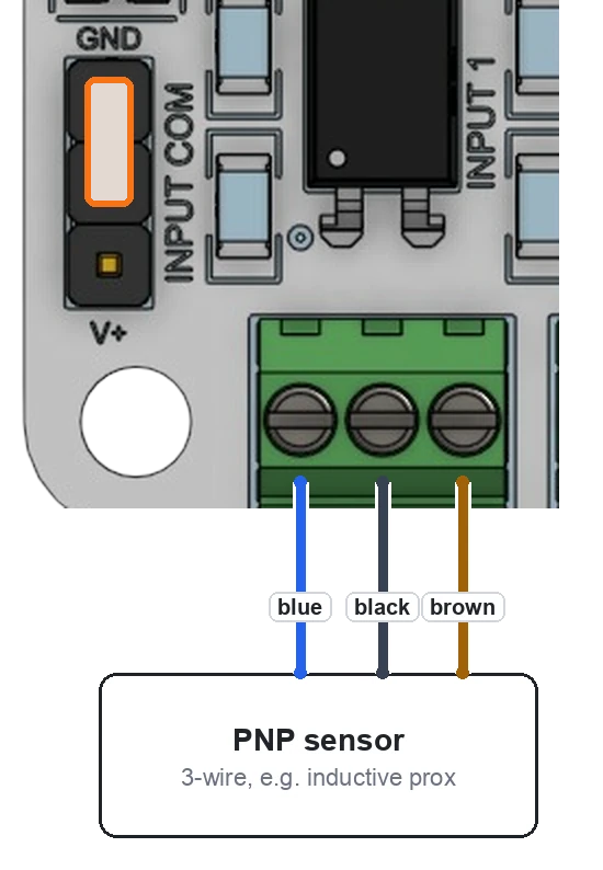
- INPUT COM on the top two pins (GND side).
- INPUT SENSOR V on the sensor's voltage.
- Brown to
V, black toS, blue toG.
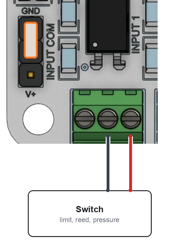
For limit switches, reed switches, pressure switches and similar dry contacts.
- INPUT COM on the top two pins (GND side).
- One switch wire to
V, the other toS.Gstays empty. - Any INPUT SENSOR V setting works.
5is gentlest on the contacts.
Outputs
Each output has a 2-screw terminal and its own voltage jumper.
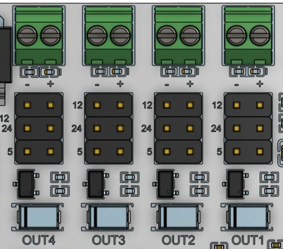
| Screw | What it does |
|---|---|
− (left) |
Connected to ground while the output is on |
+ (right) |
The voltage set by that output's jumper. Always on |
Connect the load between − and +. When ncSender turns the output on, the
load runs. Each output has a blue light, between its jumper and its terminal, that is on while the output is on.
Output voltage jumpers (OUT1 … OUT4)
Each output has its own jumper, directly above its terminal (7 in the
picture). Its rows are printed 12, 24 and 5 from the top:
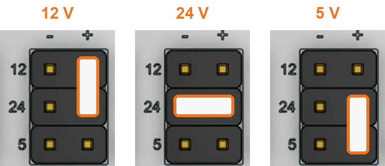
| Voltage | Shunt position |
|---|---|
| 12 V | Right column, top pair (12 and 24 rows) |
| 24 V | Across the middle row (24) |
| 5 V | Right column, bottom pair (24 and 5 rows) |
Each output can use a different voltage. From the left, the terminals are OUT4, OUT3, OUT2, OUT1.
Set the jumper before you connect the load
A 12 V solenoid on an output set to 24 runs hot and can burn out.
Sample wiring: air solenoid
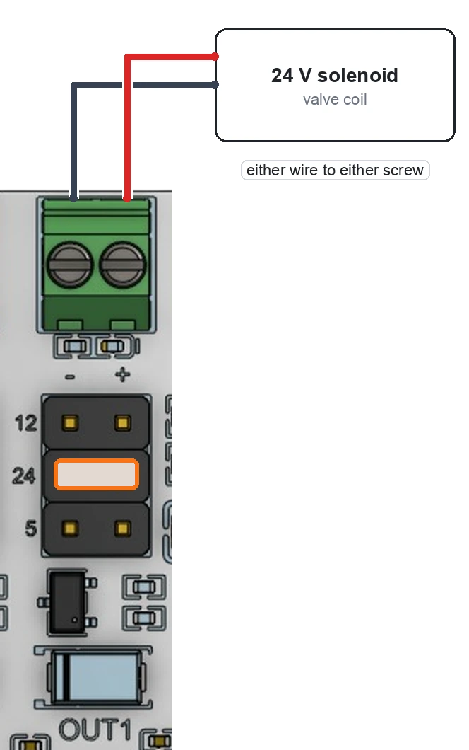
- Set the OUT1 jumper to
24, across the middle row (or to your valve's voltage). - Connect the valve's two wires to OUT1
−and+. Either way round. OUT1 is the rightmost output terminal. - Turn OUT1 on from ncSender to check the valve clicks.
Solenoids, relays and other coils are safe to connect directly. The board already has the protection diode a coil needs.
What an output can drive
- Up to about 0.8 A per output.
- Solenoid valves, relay coils, small fans, pumps, indicator lamps.
- If an output is shorted it switches off and recovers on its own once the short is removed.
- Bigger loads (spindle contactors, vacuum motors): drive a relay or contactor from the output, not the load itself.
Fail-safe
An output can be set to switch off on its own if the link to ncSender is lost, for example if the PC sleeps or the Wireless USB is unplugged. Use it for anything that should not stay on unattended.
LED strip
Plug a 12 V WS2811 strip into LED STRIP:
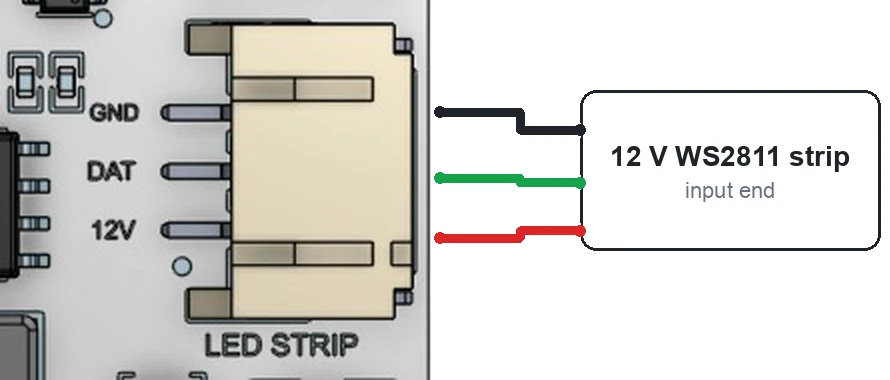
The strip works exactly like the RGB LED →: white at idle, green while running, red on an alarm, a light show when a job finishes, and so on. Set it up with the RGB LED plugin, the same way. The strip's power comes from the board through a resettable fuse.
No strip? The status light on the board shows the same colours.
Input and output mapping
| On the board | In ncSender | Light on the board |
|---|---|---|
| INPUT 1 | Input 1 | Blue, near INPUT 1 |
| INPUT 2 | Input 2 | Blue, near INPUT 2 |
| INPUT 3 | Input 3 | Blue, near INPUT 3 |
| INPUT 4 | Input 4 | Blue, near INPUT 4 |
| OUT1 (rightmost) | Output 1 | Blue, near OUT1 |
| OUT2 | Output 2 | Blue, near OUT2 |
| OUT3 | Output 3 | Blue, near OUT3 |
| OUT4 (leftmost) | Output 4 | Blue, near OUT4 |
For a pneumatic tool changer:
| Device | Connect to | Settings |
|---|---|---|
| Drawbar sensor | INPUT 1 | INPUT COM to match the sensor (NPN or PNP) |
| Tool sensor | INPUT 2 | Same |
| Clamp / unclamp solenoid | OUT1 | OUT1 jumper on the valve's voltage |
| Air pressure switch (optional) | INPUT 3 | Wire as a switch |
| Taper blow valve (optional) | OUT2 | OUT2 jumper on the valve's voltage |
Status light
The status light on the board shows the same thing the LED strip does.
| Status light | Meaning |
|---|---|
| Yellow, breathing | Not paired yet, or pairing |
| Amber, blinking | Needs activating (see Activating →) |
| White | Idle, or connected but ncSender is not sending a machine state |
| Green | Running or jogging |
| Amber | Hold |
| Red | Alarm |
| Orange | Door open |
| Teal | Probing |
| Blue | Homing |
| Magenta | Tool change |
| Changing colours, then green breathing | A job just finished |
| Blue, pulsing | Firmware update in progress. Don't power off |
Getting connected
- Plug the Wireless USB into the computer running ncSender.
- Power ncWirelessIO from PWR IN.
- In ncSender, open Accessories (the pendant icon in the toolbar) and click Pair Device. You have 60 seconds.
- On the board, hold BOOT for 3 seconds. The status light breathes
yellow while it looks for the Wireless USB.
- If BOOT is hard to reach, switch the power off and on three times quickly instead.
- Select ncWirelessIO in Accessories. It shows Connected.
- If it shows !, click Activate. See Wireless USB →.
Firmware updates
- Open Accessories and select ncWirelessIO.
- Click Update to v… in the Firmware card.
- Keep the board powered until it finishes. The status light pulses blue.
With the board plugged into the ncSender computer by USB-C, the update goes over the cable and takes about 20 seconds. Without the cable it goes wirelessly and takes over a minute. If an update is interrupted, the current firmware keeps working. Just start again.
Troubleshooting
- An input never turns on. Check its blue light while you trigger the
sensor. If the light stays off: check the INPUT COM jumper matches the
sensor (NPN or PNP), check INPUT SENSOR V is on the sensor's voltage, and
check
G,S,Vare not swapped. - An input is always on. The INPUT COM jumper is probably on the wrong side for the sensor type.
- All sensors stopped at once. The sensor supply fuse has tripped, usually a shorted sensor cable. Fix the short; it recovers by itself.
- An output's light comes on but the load doesn't run. Check the output's jumper is fitted, and that PWR IN has power. USB-C alone does not power the outputs.
- A load runs weakly. Check the output's jumper voltage, and with a 24 V supply see Power.
- Status light blinks amber. The board needs activating. See Activating →.
- Status light breathes yellow. It is not paired. See Getting connected.
Specifications
| Supply | 24–48 V DC, reverse-polarity protected |
| Inputs | 4, optically isolated, 3.3–24 V, NPN, PNP or switch |
| Sensor supply | 5, 12 or 24 V by jumper, resettable fuse |
| Outputs | 4 switched, 5, 12 or 24 V per output by jumper, about 0.8 A each, short-circuit protected |
| LED strip | 12 V WS2811, fused |
| Connection | Wireless, through the ncSender Wireless USB |
| USB | USB-C, for set-up and updates |
| Size | 70 × 68 mm |